Administration
|
|||||||||||||||||||||||||||||||||||||||||||||||||||||||||||||||||||||||||||||||||||||||||||||||||||||||||||||||||||||||||
Logical Networks |
|||||||||||||||||||||||||||||||||||||||||||||||||||||||||||||||||||||||||||||||||||||||||||||||||||||||||||||||||||||||||
Logical Network TasksPerforming Networking Tasks Network → Networks provides a central location for users to perform logical network-related operations and search for logical networks based on each network’s property or association with other resources.The New, Edit and Remove buttons allow you to create, change the properties of, and delete logical networks within data centers. Click on each network name and use the tabs in the details view to perform functions including:
These functions are also accessible through each individual resource tab. Warning: Do not change networking in a data center or a cluster if any hosts are running as this risks making the host unreachable. Important: If you plan to use oVirt nodes to provide any services, remember that the services will stop if the oVirt environment stops operating. This applies to all services, but you should be especially aware of the hazards of running the following on oVirt:
Creating a New Logical Network in a Data Center or Cluster Create a logical network and define its use in a data center, or in clusters in a data center. Creating a New Logical Network in a Data Center or Cluster
You can create an internal, isolated network, by selecting ovirt-provider-ovn on the External Provider list and leaving Connect to physical network unselected.
If you entered a label for the logical network, it is automatically added to all host network interfaces with that label. Note: When creating a new logical network or making changes to an existing logical network that is used as a display network, any running virtual machines that use that network must be rebooted before the network becomes available or the changes are applied. Editing a Logical Network Edit the settings of a logical network. Important: A logical network cannot be edited or moved to another interface if it is not synchronized with the network configuration on the host. See Editing host network interfaces on how to synchronize your networks. Editing a Logical Network
Removing a Logical Network You can remove a logical network from Network → Networks or Compute → Data Centers. The following procedure shows you how to remove logical networks associated to a data center. For a working oVirt environment, you must have at least one logical network used as the ovirtmgmt management network. Removing Logical Networks
The logical network is removed from the Engine and is no longer available. Configuring a Non-Management Logical Network as the Default Route The default route used by hosts in a cluster is through the management network (ovirtmgmt). The following procedure provides instructions to configure a non-management logical network as the default route. Prerequisite:
Configuring the Default Route Role
When networks are attached to a host, the default route of the host will be set on the network of your choice. It is recommended to configure the default route role before any host is added to your cluster. If your cluster already contains hosts, they may become out-of-sync until you sync your change to them. Viewing or Editing the Gateway for a Logical Network Users can define the gateway, along with the IP address and subnet mask, for a logical network. This is necessary when multiple networks exist on a host and traffic should be routed through the specified network, rather than the default gateway. If multiple networks exist on a host and the gateways are not defined, return traffic will be routed through the default gateway, which may not reach the intended destination. This would result in users being unable to ping the host. Multiple Gateways. oVirt handles multiple gateways automatically whenever an interface goes up or down. Viewing or Editing the Gateway for a Logical Network
The Edit Management Network window displays the network name, the boot protocol, and the IP, subnet mask, and gateway addresses. The address information can be manually edited by selecting a Static boot protocol. Logical Network General Settings Explained The table below describes the settings for the General tab of the New Logical Network and Edit Logical Network window. New Logical Network and Edit Logical Network Settings
Logical Network Cluster Settings Explained The table below describes the settings for the Cluster tab of the New Logical Network window. New Logical Network Settings
Logical Network vNIC Profiles Settings Explained The table below describes the settings for the vNIC Profiles tab of the New Logical Network window. New Logical Network Settings
Designate a Specific Traffic Type for a Logical Network with the Manage Networks Window Specify the traffic type for the logical network to optimize the network traffic flow. Specifying Traffic Types for Logical Networks
Note: Logical networks offered by external providers must be used as virtual machine networks; they cannot be assigned special cluster roles such as display or migration. Explanation of Settings in the Manage Networks Window The table below describes the settings for the Manage Networks window. Manage Networks Settings
Editing the Virtual Function Configuration on a NIC Single Root I/O Virtualization (SR-IOV) enables a single PCIe endpoint to be used as multiple separate devices. This is achieved through the introduction of two PCIe functions: physical functions (PFs) and virtual functions (VFs). A PCIe card can have between one and eight PFs, but each PF can support many more VFs (dependent on the device). You can edit the configuration of SR-IOV-capable Network Interface Controllers (NICs) through the oVirt Engine, including the number of VFs on each NIC and to specify the virtual networks allowed to access the VFs. Once VFs have been created, each can be treated as a standalone NIC. This includes having one or more logical networks assigned to them, creating bonded interfaces with them, and to directly assign vNICs to them for direct device passthrough. A vNIC must have the passthrough property enabled in order to be directly attached to a VF. See Marking vNIC as Passthrough. Editing the Virtual Function Configuration on a NIC
, and click the pencil icon.
Virtual Network Interface Cards vNIC Profile Overview A Virtual Network Interface Card (vNIC) profile is a collection of settings that can be applied to individual virtual network interface cards in the Manager. A vNIC profile allows you to apply Network QoS profiles to a vNIC, enable or disable port mirroring, and add or remove custom properties. A vNIC profile also offers an added layer of administrative flexibility in that permission to use (consume) these profiles can be granted to specific users. In this way, you can control the quality of service that different users receive from a given network. Creating or Editing a vNIC Profile Create or edit a Virtual Network Interface Controller (vNIC) profile to regulate network bandwidth for users and groups. Note: If you are enabling or disabling port mirroring, all virtual machines using the associated profile must be in a down state before editing. Creating or editing a vNIC Profile
Apply this profile to users and groups to regulate their network bandwidth. Note that if you edited a vNIC profile, you must either restart the virtual machine or hot unplug and then hot plug the vNIC. Explanation of Settings in the VM Interface Profile Window VM Interface Profile Window
. Enabling Passthrough on a vNIC Profile The passthrough property of a vNIC profile enables a vNIC to be directly connected to a virtual function (VF) of an SR-IOV-enabled NIC. The vNIC will then bypass the software network virtualization and connect directly to the VF for direct device assignment. The passthrough property cannot be enabled if the vNIC profile is already attached to a vNIC; this procedure creates a new profile to avoid this. If a vNIC profile has passthrough enabled, QoS and port mirroring are disabled for the profile. Enabling Passthrough
The vNIC profile is now passthrough-capable. To use this profile to directly attach a virtual machine to a NIC or PCI VF, attach the logical network to the NIC and create a new vNIC on the desired virtual machine that uses the passthrough vNIC profile. For more information on these procedures respectively, see “Editing host network interfaces” and “Adding a New Network Interface” in the Virtual Machine Management Guide. Removing a vNIC Profile Remove a vNIC profile to delete it from your virtualized environment. Removing a vNIC Profile
Assigning Security Groups to vNIC Profiles Note: This feature is only available for users who are integrating with OpenStack Neutron. Security groups cannot be created with oVirt Engine. You must create security groups within OpenStack. You can assign security groups to the vNIC profile of networks that have been imported from an OpenStack Networking instance and that use the Open vSwitch plug-in. A security group is a collection of strictly enforced rules that allow you to filter inbound and outbound traffic over a network interface. The following procedure outlines how to attach a security group to a vNIC profile. Note: A security group is identified using the ID of that security group as registered in the OpenStack Networking instance. You can find the IDs of security groups for a given tenant by running the following command on the system on which OpenStack Networking is installed: # neutron security-group-list Assigning Security Groups to vNIC Profiles
You have attached a security group to the vNIC profile. All traffic through the logical network to which that profile is attached will be filtered in accordance with the rules defined for that security group. User Permissions for vNIC Profiles Configure user permissions to assign users to certain vNIC profiles. Assign the VnicProfileUser role to a user to enable them to use the profile. Restrict users from certain profiles by removing their permission for that profile. User Permissions for vNIC Profiles
You have configured user permissions for a vNIC profile. Configuring vNIC Profiles for UCS Integration Cisco’s Unified Computing System (UCS) is used to manage datacenter aspects such as computing, networking and storage resources. The vdsm-hook-vmfex-dev hook allows virtual machines to connect to Cisco’s UCS-defined port profiles by configuring the vNIC profile. The UCS-defined port profiles contain the properties and settings used to configure virtual interfaces in UCS. The vdsm-hook-vmfex-dev hook is installed by default with VDSM. See VDSM and Hooks for more information. When a virtual machine that uses the vNIC profile is created, it will use the Cisco vNIC. The procedure to configure the vNIC profile for UCS integration involves first configuring a custom device property. When configuring the custom device property, any existing value it contained is overwritten. When combining new and existing custom properties, include all of the custom properties in the command used to set the key’s value. Multiple custom properties are separated by a semi-colon. Note: A UCS port profile must be configured in Cisco UCS before configuring the vNIC profile. Configuring the Custom Device Property
The vNIC profile to configure can belong to a new or existing logical network. See Creating a new logical network in a data center or cluster for instructions to configure a new logical network. Configuring a vNIC Profile for UCS Integration
External Provider Networks Importing Networks From External Providers To use networks from an external network provider (OpenStack Networking or any third-party provider that implements the OpenStack Neutron REST API), register the provider with the Manager. See Adding an OpenStack Network Service Neutron for Network Provisioning or Adding an External Network Provider for more information. Then, use the following procedure to import the networks provided by that provider into the Manager so the networks can be used by virtual machines. Importing a Network From an External Provider
The selected networks are imported into the target data center and can be attached to virtual machines. See “Adding a New Network Interface” in the Virtual Machine Management Guide for more information. Limitations to Using External Provider Networks The following limitations apply to using logical networks imported from an external provider in an oVirt environment.
Configuring Subnets on External Provider Logical Networks A logical network provided by an external provider can only assign IP addresses to virtual machines if one or more subnets have been defined on that logical network. If no subnets are defined, virtual machines will not be assigned IP addresses. If there is one subnet, virtual machines will be assigned an IP address from that subnet, and if there are multiple subnets, virtual machines will be assigned an IP address from any of the available subnets. The DHCP service provided by the external network provider on which the logical network is hosted is responsible for assigning these IP addresses. While the oVirt Engine automatically discovers predefined subnets on imported logical networks, you can also add or remove subnets to or from logical networks from within the Manager. Adding Subnets to External Provider Logical Networks Create a subnet on a logical network provided by an external provider. Adding Subnets to External Provider Logical Networks
Removing Subnets from External Provider Logical Networks Remove a subnet from a logical network provided by an external provider. Removing Subnets from External Provider Logical Networks
Hosts and Networking Refreshing Host Capabilities When a network interface card is added to a host, the capabilities of the host must be refreshed to display that network interface card in the Engine. To Refresh Host Capabilities
The list of network interface cards in the Network Interfaces tab of the details pane for the selected host is updated. Any new network interface cards can now be used in the Manager. Editing Host Network Interfaces and Assigning Logical Networks to Hosts You can change the settings of physical host network interfaces, move the management network from one physical host network interface to another, and assign logical networks to physical host network interfaces. Bridge and ethtool custom properties are also supported. Warning: The only way to change the IP address of a host in Red Hat Virtualization is to remove the host and then to add it again. Important: You cannot assign logical networks offered by external providers to physical host network interfaces; such networks are dynamically assigned to hosts as they are required by virtual machines. Note: If the switch has been configured to provide Link Layer Discovery Protocol (LLDP) information, you can hover your cursor over a physical network interface to view the switch port’s current configuration. This can help to prevent incorrect configuration. Red Hat recommends checking the following information prior to assigning logical networks:
Editing Host Network Interfaces and Assigning Logical Networks to Hosts
Alternatively, right-click the logical network and select a network interface from the drop-down menu.
Synchronizing Host Networks The Manager defines a network interface as out-of-sync when the definition of the interface on the host differs from the definitions stored by the Manager. Out-of-sync networks appear with an Out-of-sync icon
out of sync in the host’s Network Interfaces tab and with this icon out of sync setup in the Setup Host Networks window. When a host’s network is out of sync, the only activities that you can perform on the unsynchronized network in the Setup Host Networks window are detaching the logical network from the network interface or synchronizing the network. Understanding How a Host Becomes out-of-sync A host will become out of sync if:
Preventing Hosts from Becoming Unsynchronized Following these best practices will prevent your host from becoming unsynchronized:
Synchronizing Hosts Synchronizing a host’s network interface definitions involves using the definitions from the Manager and applying them to the host. If these are not the definitions that you require, after synchronizing your hosts update their definitions from the Administration Portal. You can synchronize a host’s networks on three levels:
Synchronizing Host Networks on the Logical Network Level
Synchronizing a Host’s Networks on the Host level
Synchronizing a Host’s Networks on the Cluster level
Editing a Host’s VLAN Settings To change the VLAN settings of a host, the host must be removed from the Manager, reconfigured, and re-added to the engine. To keep networking synchronized, do the following:
The following warning message appears when the VLAN ID of the management network is changed: Changing certain properties (e.g. VLAN, MTU) of the management network could lead to loss of connectivity to hosts in the data center, if its underlying network infrastructure isn't configured to accommodate the changes. Are you sure you want to proceed? Proceeding causes all of the hosts in the data center to lose connectivity to the Manager and causes the migration of hosts to the new management network to fail. The management network will be reported as “out-of-sync”. Adding Multiple VLANs to a Single Network Interface Using Logical Networks Multiple VLANs can be added to a single network interface to separate traffic on the one host. Important: You must have created more than one logical network, all with the Enable VLAN tagging check box selected in the New Logical Network or Edit Logical Network windows. Adding Multiple VLANs to a Network Interface using Logical Networks
i. Hover your cursor over an assigned logical network and click the pencil icon. ii. If your logical network definition is not synchronized with the network configuration on the host, select the Sync network check box. iii. Select a Boot Protocol:
iv. Provide the IP and Subnet Mask. v. Click OK.
Add the logical network to each host in the cluster by editing a NIC on each host in the cluster. After this is done, the network will become operational. You have added multiple VLAN-tagged logical networks to a single interface. This process can be repeated multiple times, selecting and editing the same network interface each time on each host to add logical networks with different VLAN tags to a single network interface. Assigning Additional IPv4 Addresses to a Host Network A host network, such as the ovirtmgmt management network, is created with only one IP address when initially set up. This means that if a NIC’s configuration file (for example, /etc/sysconfig/network-scripts/ifcfg-eth01) is configured with multiple IP addresses, only the first listed IP address will be assigned to the host network. Additional IP addresses may be required if connecting to storage, or to a server on a separate private subnet using the same NIC. The vdsm-hook-extra-ipv4-addrs hook allows you to configure additional IPv4 addresses for host networks. For more information about hooks, see Appendix A, VDSM and Hooks. In the following procedure, the host-specific tasks must be performed on each host for which you want to configure additional IP addresses. Assigning Additional IPv4 Addresses to a Host Network
The additional IP addresses will not be displayed in the Engine, but you can run the command ip addr show on the host to confirm that they have been added. Adding Network Labels to Host Network Interfaces Using network labels allows you to greatly simplify the administrative workload associated with assigning logical networks to host network interfaces. Note: Setting a label on a role network (for instance, a migration network or a display network) causes a mass deployment of that network on all hosts. Such mass additions of networks are achieved through the use of DHCP. This method of mass deployment was chosen over a method of typing in static addresses, because of the unscalable nature of the task of typing in many static IP addresses. Adding Network Labels to Host Network Interfaces
You have added a network label to a host network interface. Any newly created logical networks with the same label will be automatically assigned to all host network interfaces with that label. Also, removing a label from a logical network will automatically remove that logical network from all host network interfaces with that label. Bonding Logic in oVirt The oVirt Engine Administration Portal allows you to create bond devices using a graphical interface. There are several distinct bond creation scenarios, each with its own logic. Two factors that affect bonding logic are:
Bonding Scenarios and Their Results
Bonding Modes A bond is an aggregation of multiple network interface cards into a single software-defined device. Because bonded network interfaces combine the transmission capability of the network interface cards included in the bond to act as a single network interface, they can provide greater transmission speed than that of a single network interface card. Also, because all network interface cards in the bond must fail for the bond itself to fail, bonding provides increased fault tolerance. However, one limitation is that the network interface cards that form a bonded network interface must be of the same make and model to ensure that all network interface cards in the bond support the same options and modes. The packet dispersal algorithm for a bond is determined by the bonding mode used. Important: Modes 1, 2, 3, and 4 support both virtual machine (bridged) and non-virtual machine (bridgeless) network types. Modes 0, 5 and 6 support non-virtual machine (bridgeless) networks only. oVirt uses Mode 4 by default, but supports the following common bonding modes: Mode 0 (round-robin policy) Transmits packets through network interface cards in sequential order. Packets are transmitted in a loop that begins with the first available network interface card in the bond and end with the last available network interface card in the bond. All subsequent loops then start with the first available network interface card. Mode 0 offers fault tolerance and balances the load across all network interface cards in the bond. However, Mode 0 cannot be used in conjunction with bridges, and is therefore not compatible with virtual machine logical networks. Mode 1 (active-backup policy) Sets all network interface cards to a backup state while one network interface card remains active. In the event of failure in the active network interface card, one of the backup network interface cards replaces that network interface card as the only active network interface card in the bond. The MAC address of the bond in Mode 1 is visible on only one port to prevent any confusion that might otherwise be caused if the MAC address of the bond changed to reflect that of the active network interface card. Mode 1 provides fault tolerance and is supported in oVirt. Mode 2 (XOR policy) Selects the network interface card through which to transmit packets based on the result of an XOR operation on the source and destination MAC addresses modulo network interface card slave count. This calculation ensures that the same network interface card is selected for each destination MAC address used. Mode 2 provides fault tolerance and load balancing and is supported in oVirt. Mode 3 (broadcast policy) Transmits all packets to all network interface cards. Mode 3 provides fault tolerance and is supported in oVirt. Mode 4 (IEEE 802.3ad policy) Creates aggregation groups in which the interfaces share the same speed and duplex settings. Mode 4 uses all network interface cards in the active aggregation group in accordance with the IEEE 802.3ad specification and is supported in oVirt. Mode 5 (adaptive transmit load balancing policy) Ensures the distribution of outgoing traffic accounts for the load on each network interface card in the bond and that the current network interface card receives all incoming traffic. If the network interface card assigned to receive traffic fails, another network interface card is assigned to the role of receiving incoming traffic. Mode 5 cannot be used in conjunction with bridges, therefore it is not compatible with virtual machine logical networks. Mode 6 (adaptive load balancing policy) Combines Mode 5 (adaptive transmit load balancing policy) with receive load balancing for IPv4 traffic without any special switch requirements. ARP negotiation is used for balancing the receive load. Mode 6 cannot be used in conjunction with bridges, therefore it is not compatible with virtual machine logical networks. Creating a Bond Device Using the Administration Portal You can bond compatible network devices together. This type of configuration can increase available bandwidth and reliability. You can bond multiple network interfaces, pre-existing bond devices, and combinations of the two. A bond can carry both VLAN tagged and non-VLAN traffic. Creating a Bond Device using the Administration Portal
Your network devices are linked into a bond device and can be edited as a single interface. The bond device is listed in the Network Interfaces tab of the details pane for the selected host. Bonding must be enabled for the ports of the switch used by the host. The process by which bonding is enabled is slightly different for each switch; consult the manual provided by your switch vendor for detailed information on how to enable bonding. Note: For a bond in Mode 4, all slaves must be configured properly on the switch. If none of them is configured properly on the switch, the ad_partner_mac is reported as 00:00:00:00:00:00. The Manager will display a warning in the form of an exclamation mark icon on the bond in the Network Interfaces tab. No warning is provided if any of the slaves are up and running. Example Uses of Custom Bonding Options with Host Interfaces You can create customized bond devices by selecting Custom from the Bonding Mode of the Create New Bond window. The following examples should be adapted for your needs. For a comprehensive list of bonding options and their descriptions, see the Linux Ethernet Bonding Driver HOWTO on Kernel.org. xmit_hash_policy This option defines the transmit load balancing policy for bonding modes 2 and 4. For example, if the majority of your traffic is between many different IP addresses, you may want to set a policy to balance by IP address. You can set this load-balancing policy by selecting a Custom bonding mode, and entering the following into the text field: mode=4 xmit_hash_policy=layer2+3 ARP Monitoring ARP monitor is useful for systems which can’t or don’t report link-state properly via ethtool. Set an arp_interval on the bond device of the host by selecting a Custom bonding mode, and entering the following into the text field: mode=1 arp_interval=1 arp_ip_target=192.168.0.2 Primary You may want to designate a NIC with higher throughput as the primary interface in a bond device. Designate which NIC is primary by selecting a Custom bonding mode, and entering the following into the text field: mode=1 primary=eth0 Changing the FQDN of a Host Use the following procedure to change the fully qualified domain name of hosts. Updating the FQDN of a Host
|
|||||||||||||||||||||||||||||||||||||||||||||||||||||||||||||||||||||||||||||||||||||||||||||||||||||||||||||||||||||||||
Data Centers |
|||||||||||||||||||||||||||||||||||||||||||||||||||||||||||||||||||||||||||||||||||||||||||||||||||||||||||||||||||||||||
|
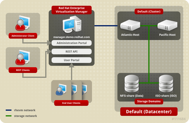
Introduction to Data Centers A data center is a logical entity that defines the set of resources used in a specific environment. A data center is considered a container resource, in that it is comprised of logical resources, in the form of clusters and hosts; network resources, in the form of logical networks and physical NICs; and storage resources, in the form of storage domains. A data center can contain multiple clusters, which can contain multiple hosts; it can have multiple storage domains associated to it; and it can support multiple virtual machines on each of its hosts. An oVirt environment can contain multiple data centers; the data center infrastructure allows you to keep these centers separate. All data centers are managed from the single Administration Portal. Data Centers
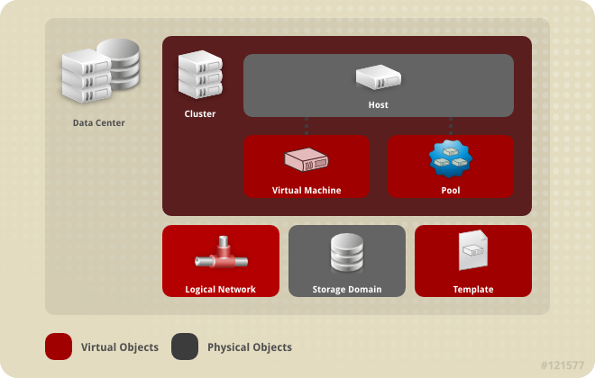
oVirt creates a default data center during installation. You can configure the default data center, or set up new appropriately named data centers. Data Center Objects
The Storage Pool Manager The Storage Pool Manager (SPM) is a role given to one of the hosts in the data center enabling it to manage the storage domains of the data center. The SPM entity can be run on any host in the data center; the oVirt Engine grants the role to one of the hosts. The SPM does not preclude the host from its standard operation; a host running as SPM can still host virtual resources. The SPM entity controls access to storage by coordinating the metadata across the storage domains. This includes creating, deleting, and manipulating virtual disks (images), snapshots, and templates, and allocating storage for sparse block devices (on SAN). This is an exclusive responsibility: only one host can be the SPM in the data center at one time to ensure metadata integrity. The oVirt Engine ensures that the SPM is always available. The Manager moves the SPM role to a different host if the SPM host encounters problems accessing the storage. When the SPM starts, it ensures that it is the only host granted the role; therefore it will acquire a storage-centric lease. This process can take some time. SPM Priority The SPM role uses some of a host’s available resources. The SPM priority setting of a host alters the likelihood of the host being assigned the SPM role: a host with high SPM priority will be assigned the SPM role before a host with low SPM priority. Critical virtual machines on hosts with low SPM priority will not have to contend with SPM operations for host resources. You can change a host’s SPM priority in the SPM tab in the Edit Host window. Data Center Tasks Creating a New Data Center This procedure creates a data center in your virtualization environment. The data center requires a functioning cluster, host, and storage domain to operate. **Note:** Once the **Compatibility Version** is set, it cannot be lowered at a later time; version regression is not allowed. The option to specify a MAC pool range for a data center has been disabled, and is now done at the cluster level. Creating a New Data Center
The new data center is added to the virtualization environment. It will remain Uninitialized until a cluster, host, and storage domain are configured for it; use Guide Me to configure these entities. Explanation of Settings in the New Data Center and Edit Data Center Windows The table below describes the settings of a data center as displayed in the New Data Center and Edit Data Center windows. Invalid entries are outlined in orange when you click OK, prohibiting the changes being accepted. In addition, field prompts indicate the expected values or range of values. Data Center Properties
Re-Initializing a Data Center: Recovery Procedure This recovery procedure replaces the master data domain of your data center with a new master data domain; necessary in the event of data corruption of your master data domain. Re-initializing a data center allows you to restore all other resources associated with the data center, including clusters, hosts, and non-problematic storage domains. You can import any backup or exported virtual machines or templates into your new master data domain. Re-Initializing a Data Center
The storage domain is attached to the data center as the master data domain and activated. You can now import any backup or exported virtual machines or templates into your new master data domain. Removing a Data Center An active host is required to remove a data center. Removing a data center will not remove the associated resources. Removing a Data Center
Force Removing a Data Center A data center becomes Non Responsive if the attached storage domain is corrupt or if the host becomes Non Responsive. You cannot Remove the data center under either circumstance. Force Remove does not require an active host. It also permanently removes the attached storage domain. It may be necessary to Destroy a corrupted storage domain before you can Force Remove the data center. Force Removing a Data Center
The data center and attached storage domain are permanently removed from the oVirt environment. Changing the Data Center Storage Type You can change the storage type of the data center after it has been initialized. This is useful for data domains that are used to move virtual machines or templates around. Limitations
Changing the Data Center Storage Type
Changing the Data Center Compatibility Version oVirt data centers have a compatibility version. The compatibility version indicates the version of oVirt that the data center is intended to be compatible with. All clusters in the data center must support the desired compatibility level. Important: To change the data center compatibility version, you must have first updated all the clusters in your data center to a level that supports your desired compatibility level. Procedure
You have updated the compatibility version of the data center. Important: Upgrading the compatibility will also upgrade all of the storage domains belonging to the data center. Data Centers and Storage Domains Attaching an Existing Data Domain to a Data Center Data domains that are Unattached can be attached to a data center. Shared storage domains of multiple types (iSCSI, NFS, FC, POSIX, and Gluster) can be added to the same data center. Attaching an Existing Data Domain to a Data Center
The data domain is attached to the data center and is automatically activated. Attaching an Existing ISO domain to a Data Center An ISO domain that is Unattached can be attached to a data center. The ISO domain must be of the same Storage Type as the data center. Only one ISO domain can be attached to a data center. Attaching an Existing ISO Domain to a Data Center
The ISO domain is attached to the data center and is automatically activated. Attaching an Existing Export Domain to a Data Center **Note:** The export storage domain is deprecated. Storage data domains can be unattached from a data center and imported to another data center in the same environment, or in a different environment. Virtual machines, floating virtual disk images, and templates can then be uploaded from the imported storage domain to the attached data center. See [Importing Existing Storage Domains](sect-Importing_Existing_Storage_Domains) for information on importing storage domains. An export domain that is Unattached can be attached to a data center. Only one export domain can be attached to a data center. Attaching an Existing Export Domain to a Data Center
The export domain is attached to the data center and is automatically activated. Detaching a Storage Domain from a Data Center Detaching a storage domain from a data center will stop the data center from associating with that storage domain. The storage domain is not removed from the oVirt environment; it can be attached to another data center. Data, such as virtual machines and templates, remains attached to the storage domain. Note: The master storage, if it is the last available storage domain, cannot be removed. Detaching a Storage Domain from a Data Center
You have detached the storage domain from the data center. It can take up to several minutes for the storage domain to disappear from the details pane.
Data Centers and Permissions Managing System Permissions for a Data Center As the SuperUser, the system administrator manages all aspects of the Administration Portal. More specific administrative roles can be assigned to other users. These restricted administrator roles are useful for granting a user administrative privileges that limit them to a specific resource. For example, a DataCenterAdmin role has administrator privileges only for the assigned data center with the exception of the storage for that data center, and a ClusterAdmin has administrator privileges only for the assigned cluster. A data center administrator is a system administration role for a specific data center only. This is useful in virtualization environments with multiple data centers where each data center requires an administrator. The DataCenterAdmin role is a hierarchical model; a user assigned the data center administrator role for a data center can manage all objects in the data center with the exception of storage for that data center. Use the Configure button in the header bar to assign a data center administrator for all data centers in the environment. The data center administrator role permits the following actions:
Note: You can only assign roles and permissions to existing users. You can change the system administrator of a data center by removing the existing system administrator and adding the new system administrator. Data Center Administrator Roles Explained Data Center Permission Roles The table below describes the administrator roles and privileges applicable to data center administration. oVirt System Administrator Roles
Assigning an Administrator or User Role to a Resource Assign administrator or user roles to resources to allow users to access or manage that resource. Assigning a Role to a Resource
You have assigned a role to a user; the user now has the inherited permissions of that role enabled for that resource. Removing an Administrator or User Role from a Resource Remove an administrator or user role from a resource; the user loses the inherited permissions associated with the role for that resource. Removing a Role from a Resource
You have removed the user's role, and the associated permissions, from the resource.
|
|||||||||||||||||||||||||||||||||||||||||||||||||||||||||||||||||||||||||||||||||||||||||||||||||||||||||||||||||||||||||
Clusters |
|||||||||||||||||||||||||||||||||||||||||||||||||||||||||||||||||||||||||||||||||||||||||||||||||||||||||||||||||||||||||
|
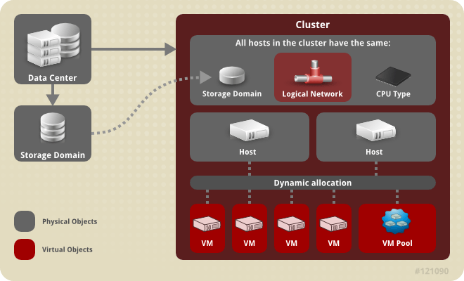
Introduction to Clusters A cluster is a logical grouping of hosts that share the same storage domains and have the same type of CPU (either Intel or AMD). If the hosts have different generations of CPU models, they use only the features present in all models. Each cluster in the system must belong to a data center, and each host in the system must belong to a cluster. Virtual machines are dynamically allocated to any host in a cluster and can be migrated between them, according to policies defined on the Clusters tab and in the Configuration tool during runtime. The cluster is the highest level at which power and load-sharing policies can be defined. The number of hosts and number of virtual machines that belong to a cluster are displayed in the results list under Host Count and VM Count, respectively. Clusters run virtual machines or Gluster Storage Servers. These two purposes are mutually exclusive: A single cluster cannot support virtualization and storage hosts together. oVirt creates a default cluster in the default data center during installation. Cluster
Cluster Tasks Creating a New Cluster A data center can contain multiple clusters, and a cluster can contain multiple hosts. All hosts in a cluster must be of the same CPU type (Intel or AMD). It is recommended that you create your hosts before you create your cluster to ensure CPU type optimization. However, you can configure the hosts at a later time using the Guide Me button. Creating a New Cluster Select the Clusters resource tab. Click New. Select the Data Center the cluster will belong to from the drop-down list. Enter the Name and Description of the cluster. Select a network from the Management Network drop-down list to assign the management network role. Select the CPU Architecture and CPU Type from the drop-down lists. It is important to match the CPU processor family with the minimum CPU processor type of the hosts you intend to attach to the cluster, otherwise the host will be non-operational. Note: For both Intel and AMD CPU types, the listed CPU models are in logical order from the oldest to the newest. If your cluster includes hosts with different CPU models, select the oldest CPU model. Select the Compatibility Version of the cluster from the drop-down list. Select either the Enable Virt Service or Enable Gluster Service radio button to define whether the cluster will be populated with virtual machine hosts or with Gluster-enabled nodes. Optionally select the Enable to set VM maintenance reason check box to enable an optional reason field when a virtual machine is shut down from the Manager, allowing the administrator to provide an explanation for the maintenance. Optionally select the Enable to set Host maintenance reason check box to enable an optional reason field when a host is placed into maintenance mode from the Manager, allowing the administrator to provide an explanation for the maintenance. Select either the /dev/random source (Linux-provided device) or /dev/hwrng source (external hardware device) check box to specify the random number generator device that all hosts in the cluster will use. Click the Optimization tab to select the memory page sharing threshold for the cluster, and optionally enable CPU thread handling and memory ballooning on the hosts in the cluster. Click the Migration Policy tab to define the virtual machine migration policy for the cluster. Click the Scheduling Policy tab to optionally configure a scheduling policy, configure scheduler optimization settings, enable trusted service for hosts in the cluster, enable HA Reservation, and add a custom serial number policy. Click the Console tab to optionally override the global SPICE proxy, if any, and specify the address of a SPICE proxy for hosts in the cluster. Click the Fencing policy tab to enable or disable fencing in the cluster, and select fencing options. Click OK to create the cluster and open the New Cluster - Guide Me window. The Guide Me window lists the entities that need to be configured for the cluster. Configure these entities or postpone configuration by clicking the Configure Later button; configuration can be resumed by selecting the cluster and clicking the Guide Me button. The new cluster is added to the virtualization environment. Explanation of Settings and Controls in the New Cluster and Edit Cluster Windows General Cluster Settings Explained
The table below describes the settings for the General tab in the New Cluster and Edit Cluster windows. Invalid entries are outlined in orange when you click OK, prohibiting the changes being accepted. In addition, field prompts indicate the expected values or range of values. General Cluster Settings
Optimization Settings Explained Memory page sharing allows virtual machines to use up to 200% of their allocated memory by utilizing unused memory in other virtual machines. This process is based on the assumption that the virtual machines in your oVirt environment will not all be running at full capacity at the same time, allowing unused memory to be temporarily allocated to a particular virtual machine. CPU Thread Handling allows hosts to run virtual machines with a total number of processor cores greater than number of cores in the host. This is useful for non-CPU-intensive workloads, where allowing a greater number of virtual machines to run can reduce hardware requirements. It also allows virtual machines to run with CPU topologies that would otherwise not be possible, specifically if the number of guest cores is between the number of host cores and number of host threads. The table below describes the settings for the Optimization tab in the New Cluster and Edit Cluster windows. Optimization Settings
Migration Policy Settings Explained A migration policy defines the conditions for live migrating virtual machines in the event of host failure. These conditions include the downtime of the virtual machine during migration, network bandwidth, and how the virtual machines are prioritized. Migration Policies Explained
The bandwidth settings define the maximum bandwidth of both outgoing and incoming migrations per host. Bandwidth Explained
The resilience policy defines how the virtual machines are prioritized in the migration. Resilience Policy Settings
The Additional Properties are only applicable to the Legacy migration policy. Additional Properties Explained
Scheduling Policy Settings Explained Scheduling policies allow you to specify the usage and distribution of virtual machines between available hosts. Define the scheduling policy to enable automatic load balancing across the hosts in a cluster. To add a scheduling policy to an existing cluster, click the Clusters tab and click the Edit button, then click the Scheduling Policy tab.
The table below describes the settings for the Scheduling Policy tab. Scheduling Policy Tab Properties
When a host's free memory drops below 20%, ballooning tts like mom.Controllers.Balloon - INFO Ballooning guest:half1 from 1096400 to 1991580 are logged to /var/log/vdsm/mom.log. /var/log/vdsm/mom.log is the Memory Overcommit Manager log file. Cluster Console Settings Explained The table below describes the settings for the Console tab in the New Cluster and Edit Cluster windows. Console Settings
Fencing Policy Settings Explained The table below describes the settings for the Fencing Policy tab in the New Cluster and Edit Cluster windows. Fencing Policy Settings
Editing a Resource Summary Edit the properties of a resource. Editing a Resource Use the resource tabs, tree mode, or the search function to find and select the resource in the results list. Click Edit to open the Edit window. Change the necessary properties and click OK. Result The new properties are saved to the resource. The Edit window will not close if a property field is invalid. Setting Load and Power Management Policies for Hosts in a Cluster The evenly_distributed and power_saving scheduling policies allow you to specify acceptable memory and CPU usage values, and the point at which virtual machines must be migrated to or from a host. The vm_evenly_distributed scheduling policy distributes virtual machines evenly between hosts based on a count of the virtual machines. Define the scheduling policy to enable automatic load balancing across the hosts in a cluster. For a detailed explanation of each scheduling policy, see Cluster Scheduling Policy Settings. Setting Load and Power Management Policies for Hosts Use the resource tabs, tree mode, or the search function to find and select the cluster in the results list. Click Edit to open the Edit Cluster window.
Select one of the following policies: none vm_evenly_distributed Set the maximum number of virtual machines that can run on each host in the HighVmCount field. Define the maximum acceptable difference between the number of virtual machines on the most highly-utilized host and the number of virtual machines on the least-utilized host in the MigrationThreshold field. Define the number of slots for virtual machines to be reserved on SPM hosts in the SpmVmGrace field. evenly_distributed Set the time (in minutes) that a host can run a CPU load outside of the defined utilization values before the scheduling policy takes action in the CpuOverCommitDurationMinutes field. Enter the CPU utilization percentage at which virtual machines start migrating to other hosts in the HighUtilization field. Enter the minimum required free memory in MB at which virtual machines start migrating to other hosts in the MinFreeMemoryForUnderUtilized. Enter the maximum required free memory in MB at which virtual machines start migrating to other hosts in the MaxFreeMemoryForOverUtilized. power_saving Set the time (in minutes) that a host can run a CPU load outside of the defined utilization values before the scheduling policy takes action in the CpuOverCommitDurationMinutes field. Enter the CPU utilization percentage below which the host will be considered under-utilized in the LowUtilization field. Enter the CPU utilization percentage at which virtual machines start migrating to other hosts in the HighUtilization field. Enter the minimum required free memory in MB at which virtual machines start migrating to other hosts in the MinFreeMemoryForUnderUtilized. Enter the maximum required free memory in MB at which virtual machines start migrating to other hosts in the MaxFreeMemoryForOverUtilized. Choose one of the following as the Scheduler Optimization for the cluster: Select Optimize for Utilization to include weight modules in scheduling to allow best selection. Select Optimize for Speed to skip host weighting in cases where there are more than ten pending requests. If you are using an OpenAttestation server to verify your hosts, and have set up the server's details using the engine-config tool, select the Enable Trusted Service check box. Optionally select the Enable HA Reservation check box to enable the Manager to monitor cluster capacity for highly available virtual machines. Optionally select the Provide custom serial number policy check box to specify a serial number policy for the virtual machines in the cluster, and then select one of the following options: Select Host ID to set the host's UUID as the virtual machine's serial number. Select Vm ID to set the virtual machine's UUID as its serial number. Select Custom serial number, and then specify a custom serial number in the text field. Click OK. Updating the MoM Policy on Hosts in a Cluster The Memory Overcommit Manager handles memory balloon and KSM functions on a host. Changes to these functions at the cluster level are only passed to hosts the next time a host moves to a status of Up after being rebooted or in maintenance mode. However, if necessary you can apply important changes to a host immediately by synchronizing the MoM policy while the host is Up. The following procedure must be performed on each host individually. Synchronizing MoM Policy on a Host Click the Clusters tab and select the cluster to which the host belongs. Click the Hosts tab in the details pane and select the host that requires an updated MoM policy. Click Sync MoM Policy. The MoM policy on the host is updated without having to move the host to maintenance mode and back Up. CPU Profiles CPU profiles define the maximum amount of processing capability a virtual machine in a cluster can access on the host on which it runs, expressed as a percent of the total processing capability available to that host. CPU profiles are created based on CPU profiles defined under data centers, and are not automatically applied to all virtual machines in a cluster; they must be manually assigned to individual virtual machines for the profile to take effect. Creating a CPU Profile Create a CPU profile. This procedure assumes you have already defined one or more CPU quality of service entries under the data center to which the cluster belongs. Creating a CPU Profile Click the Clusters resource tab and select a cluster. Click the CPU Profiles sub tab in the details pane. Click New. Enter a name for the CPU profile in the Name field. Enter a description for the CPU profile in the Description field. Select the quality of service to apply to the CPU profile from the QoS list. Click OK. You have created a CPU profile, and that CPU profile can be applied to virtual machines in the cluster. Removing a CPU Profile Remove an existing CPU profile from your oVirt environment. Removing a CPU Profile Click the Clusters resource tab and select a cluster. Click the CPU Profiles sub tab in the details pane. Select the CPU profile to remove. Click Remove. Click OK. You have removed a CPU profile, and that CPU profile is no longer available. If the CPU profile was assigned to any virtual machines, those virtual machines are automatically assigned the default CPU profile. Importing an Existing Gluster Storage Cluster You can import a Gluster Storage cluster and all hosts belonging to the cluster into oVirt Engine. When you provide details such as the IP address or host name and password of any host in the cluster, the gluster peer status command is executed on that host through SSH, then displays a list of hosts that are a part of the cluster. You must manually verify the fingerprint of each host and provide passwords for them. You will not be able to import the cluster if one of the hosts in the cluster is down or unreachable. As the newly imported hosts do not have VDSM installed, the bootstrap script installs all the necessary VDSM packages on the hosts after they have been imported, and reboots them. Importing an Existing Gluster Storage Cluster to oVirt Engine Select the Clusters resource tab to list all clusters in the results list. Click New to open the New Cluster window. Select the Data Center the cluster will belong to from the drop-down menu. Enter the Name and Description of the cluster. Select the Enable Gluster Service radio button and the Import existing gluster configuration check box. The Import existing gluster configuration field is displayed only if you select Enable Gluster Service radio button. In the Address field, enter the hostname or IP address of any server in the cluster. The host Fingerprint displays to ensure you are connecting with the correct host. If a host is unreachable or if there is a network error, an error Error in fetching fingerprint displays in the Fingerprint field. Enter the Root Password for the server, and click OK. The Add Hosts window opens, and a list of hosts that are a part of the cluster displays. For each host, enter the Name and the Root Password. If you wish to use the same password for all hosts, select the Use a Common Password check box to enter the password in the provided text field. Click Apply to set the entered password all hosts. Make sure the fingerprints are valid and submit your changes by clicking OK. The bootstrap script installs all the necessary VDSM packages on the hosts after they have been imported, and reboots them. You have now successfully imported an existing Gluster Storage cluster into oVirt Engine. Explanation of Settings in the Add Hosts Window The Add Hosts window allows you to specify the details of the hosts imported as part of a Gluster-enabled cluster. This window appears after you have selected the Enable Gluster Service check box in the New Cluster window and provided the necessary host details. Add Gluster Hosts Settings
Removing a Cluster Summary Move all hosts out of a cluster before removing it. Note: You cannot remove the Default cluster, as it holds the Blank template. You can however rename the Default cluster and add it to a new data center. Removing a Cluster Use the resource tabs, tree mode, or the search function to find and select the cluster in the results list. Ensure there are no hosts in the cluster. Click Remove to open the Remove Cluster(s) confirmation window. Click OK Result The cluster is removed. Changing the Cluster Compatibility Version oVirt clusters have a compatibility version. The cluster compatibility version indicates the features of oVirt supported by all of the hosts in the cluster. The cluster compatibility is set according to the version of the least capable host operating system in the cluster. Note: To change the cluster compatibility version, you must have first updated all the hosts in your cluster to a level that supports your desired compatibility level. Changing the Cluster Compatibility Version From the Administration Portal, click the Clusters tab. Select the cluster to change from the list displayed. Click Edit. Change the Compatibility Version to the desired value. Click OK to open the Change Cluster Compatibility Version confirmation window. Click OK to confirm. You have updated the compatibility version of the cluster. Once you have updated the compatibility version of all clusters in a data center, you can then change the compatibility version of the data center itself. Important: Upgrading the compatibility will also upgrade all of the storage domains belonging to the data center. Clusters and Permissions Managing System Permissions for a Cluster As the SuperUser, the system administrator manages all aspects of the Administration Portal. More specific administrative roles can be assigned to other users. These restricted administrator roles are useful for granting a user administrative privileges that limit them to a specific resource. For example, a DataCenterAdmin role has administrator privileges only for the assigned data center with the exception of the storage for that data center, and a ClusterAdmin has administrator privileges only for the assigned cluster. A cluster administrator is a system administration role for a specific data center only. This is useful in data centers with multiple clusters, where each cluster requires a system administrator. The ClusterAdmin role is a hierarchical model: a user assigned the cluster administrator role for a cluster can manage all objects in the cluster. Use the Configure button in the header bar to assign a cluster administrator for all clusters in the environment. The cluster administrator role permits the following actions: Create and remove associated clusters. Add and remove hosts, virtual machines, and pools associated with the cluster. Edit user permissions for virtual machines associated with the cluster. Note: You can only assign roles and permissions to existing users. You can also change the system administrator of a cluster by removing the existing system administrator and adding the new system administrator. Cluster Administrator Roles Explained Cluster Permission Roles The table below describes the administrator roles and privileges applicable to cluster administration. oVirt System Administrator Roles
Assigning an Administrator or User Role to a Resource Assign administrator or user roles to resources to allow users to access or manage that resource. Assigning a Role to a Resource Use the resource tabs, tree mode, or the search function to find and select the resource in the results list. Click the Permissions tab in the details pane to list the assigned users, the user's role, and the inherited permissions for the selected resource. Click Add. Enter the name or user name of an existing user into the Search text box and click Go. Select a user from the resulting list of possible matches. Select a role from the Role to Assign: drop-down list. Click OK. You have assigned a role to a user; the user now has the inherited permissions of that role enabled for that resource. Removing an Administrator or User Role from a Resource Remove an administrator or user role from a resource; the user loses the inherited permissions associated with the role for that resource. Removing a Role from a Resource Use the resource tabs, tree mode, or the search function to find and select the resource in the results list. Click the Permissions tab in the details pane to list the assigned users, the user's role, and the inherited permissions for the selected resource. Select the user to remove from the resource. Click Remove. The Remove Permission window opens to confirm permissions removal. Click OK. You have removed the user's role, and the associated permissions, from the resource.
|
|||||||||||||||||||||||||||||||||||||||||||||||||||||||||||||||||||||||||||||||||||||||||||||||||||||||||||||||||||||||||
Storage |
|||||||||||||||||||||||||||||||||||||||||||||||||||||||||||||||||||||||||||||||||||||||||||||||||||||||||||||||||||||||||
If you do not yet have an appropriate FCP data center, select (none).
ImportantAll communication to the storage domain is through the selected host and not directly from the Red Hat Virtualization Manager. At least one active host must exist in the system and be attached to the chosen data center. All hosts must have access to the storage device before the storage domain can be configured.
The new FCP data domain displays in Storage → Domains. It will remain with a Locked status while it is being prepared for use. When ready, it is automatically attached to the data center.
/var/lib/exports/iso 10.1.2.0/255.255.255.0(rw) host01.example.com(rw) host02.example.com(rw)The example above allows read and write access to a single /24 network and two specific hosts. /var/lib/exports/iso is the default file path for the ISO domain. See the exports(5) man page for further formatting options.
exportfs -ra or -avshowmount -eNote that if you manually edit the /etc/exports file after running engine-setup, running engine-cleanup later will not undo the changes.
The ISO domain is now attached to the data center and is automatically activated.
subscription-manager register
subscription-manager list --available
subscription-manager attach --pool=poolidNoteTo find out which subscriptions are currently attached, run:subscription-manager list --consumedTo list all enabled repositories, run:yum repolist
subscription-manager repos --disable=*
subscription-manager repos --enable=rhel-7-server-rpmssubscription-manager repos --enable=rhel-7-server-rhv-4.2-manager-rpms
yum install rh-postgresql95 rh-postgresql95-postgresql-contrib
scl enable rh-postgresql95 -- postgresql-setup --initdbsystemctl enable rh-postgresql95-postgresqlsystemctl start rh-postgresql95-postgresql
su - postgres -c 'scl enable rh-postgresql95 -- psql'
postgres=# create role user_name with login encrypted password 'password';
postgres=# create database database_name owner user_name template template0 encoding 'UTF8' lc_collate 'en_US.UTF-8' lc_ctype 'en_US.UTF-8';
postgres=# \c database_name
database_name=# CREATE EXTENSION "uuid-ossp";
database_name=# CREATE LANGUAGE plpgsql;
host database_name user_name ::0/32 md5host database_name user_name ::0/128 md5
listen_addresses='*'
autovacuum_vacuum_scale_factor='0.01'autovacuum_analyze_scale_factor='0.075'autovacuum_max_workers='6'maintenance_work_mem='65536'max_connections='150'work_mem='8192'
firewall-cmd --zone=public --add-service=postgresqlfirewall-cmd --permanent --zone=public --add-service=postgresql
systemctl rh-postgresql95-postgresql restart
subscription-manager register
subscription-manager list --available
subscription-manager attach --pool=poolidNoteTo find out which subscriptions are currently attached, run:subscription-manager list --consumedTo list all enabled repositories, run:yum repolist
subscription-manager repos --disable=*
subscription-manager repos --enable=rhel-7-server-rpmssubscription-manager repos --enable=rhel-7-server-rhv-4.2-manager-rpms
yum install rh-postgresql95 rh-postgresql95-postgresql-contrib
scl enable rh-postgresql95 -- postgresql-setup --initdbsystemctl enable rh-postgresql95-postgresqlsystemctl start rh-postgresql95-postgresql
su - postgres -c 'scl enable rh-postgresql95 -- psql'
postgres=# create role user_name with login encrypted password 'password';
postgres=# create database database_name owner user_name template template0 encoding 'UTF8' lc_collate 'en_US.UTF-8' lc_ctype 'en_US.UTF-8';
postgres=# \c database_name
database_name=# CREATE EXTENSION "uuid-ossp";
database_name=# CREATE LANGUAGE plpgsql;
host [database name] [user name] 0.0.0.0/0 md5host [database name] [user name] ::/32 md5host [database name] [user name] ::/128 md5
autovacuum_vacuum_scale_factor='0.01'autovacuum_analyze_scale_factor='0.075'autovacuum_max_workers='6'maintenance_work_mem='65536'max_connections='150'work_mem='8192'
systemctl rh-postgresql95-postgresql restart |